Cross-eye
A “Twin RX/TX Apertures” antenna system is based on two RX/TX phased array antennas located in different positions (forming a baseline L) and feeding a dual DRFM.
Exploiting the solid-state architecture gives the ability to control accurately the relative phase and amplitude of jamming signals at the level needed to implement X-E technique.
The X-E jammer is composed by two separate repeaters (separated by a distance L) each equipped with two sets of antennas (receiving and transmitting): the signal received by set 1 is connected to the transmitting antenna of set 2 by means of a line and an amplifier and vice-versa for the signal received by set 2.
To give an example, in case of a fighter installation the two couples of antennas are mounted on the wingtips in order to obtain the maximum possible distance (Figure 1).
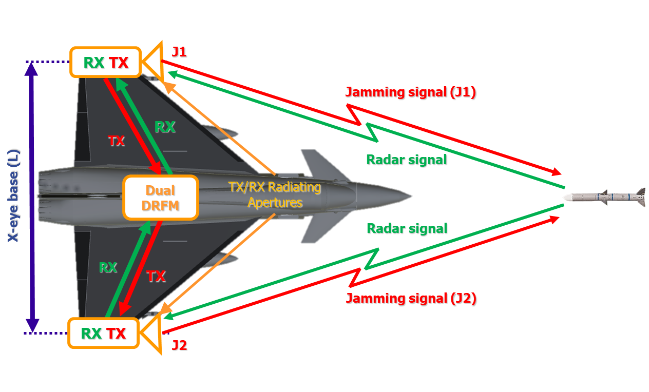
Figure 1: Example of Fighter A/C installation
X-E effect is obtained by the simultaneous transmission (from the X-E baseline L) of the two repeated signals J1 and J2 with a small unbalance in transmitted power (PJ1/PJ2 < 1÷2 dB) and in counter-phase (ΦJ1 – ΦJ2 = 180°).
The choice of the “strong” X-E source J1 or J2 is based on the threat Direction of Arrival and it imposes the false target relative positioning w.r.t the baseline (right or left side).
Due to the ratio of the range R between the Radar and the jammer and the distance L between the two X-E antennas (R>>L) the two X-E antennas cannot be resolved individually by the victim radar, that always sees the sum of the jamming signals.
If the victim radar has the target in the bore-sight, the signal in the Σ channel will be about null due to the interferometric cancellation created by the jammer and therefore the mono-pulse Δ/Σ (Delta channel on Sigma channel amplitude ratio) tends to infinite.
This condition creates a local distortion in the phase front that takes place in a narrow angular region surrounding the radar antenna center of phase, deceiving the radar from the real position of the platform carrying the jammer.
The boresight of the radar points to a direction perpendicular (normal) to the phase front and, because of the X-E distortion effect, it does not point to the platform equipped with the jammer system but to a false target point, at a constant distance offset (D) from the real target position (Figure 2).
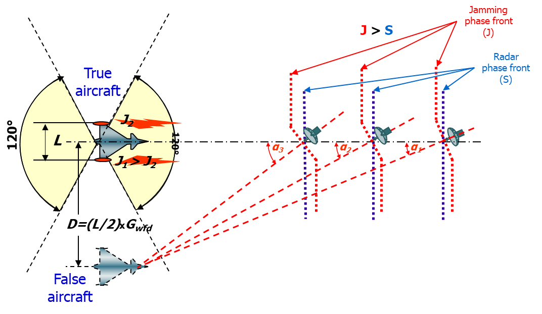
Figure 2: Example of X-E effect
The relative amplitude of the two X-E transmitted signals can be changed on a real time basis and the relative phase as well, creating blinking false targets.
Possible drawbacks of the cross-eye technique:
-
In theory, the maximum effectiveness is obtained when the direction of origin of the two jamming signals are less parallel, i.e. when the angle subtended by the jamming antennas is maximum, which occurs only when the target gets closer to the victim radar.
-
The technique creates an interferometer null in the missile radar Σ channel that could allow the detection of the skin echo of the target in case of insufficient J/S ratio.