Anti-Monopulse techniques – Cross-polarization
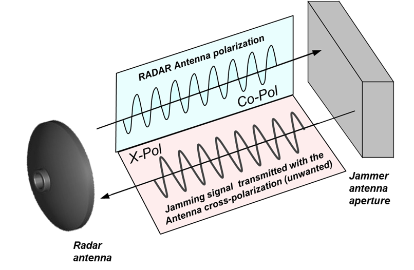
The goal of cross-polarization is to cause angular measurement errors in the victim mono-pulse radar by radiating a jamming signal that is polarized orthogonally with respect to the polarization of the radar antenna (Figure 1).

Figure 1: Example of Cross-Pol jamming
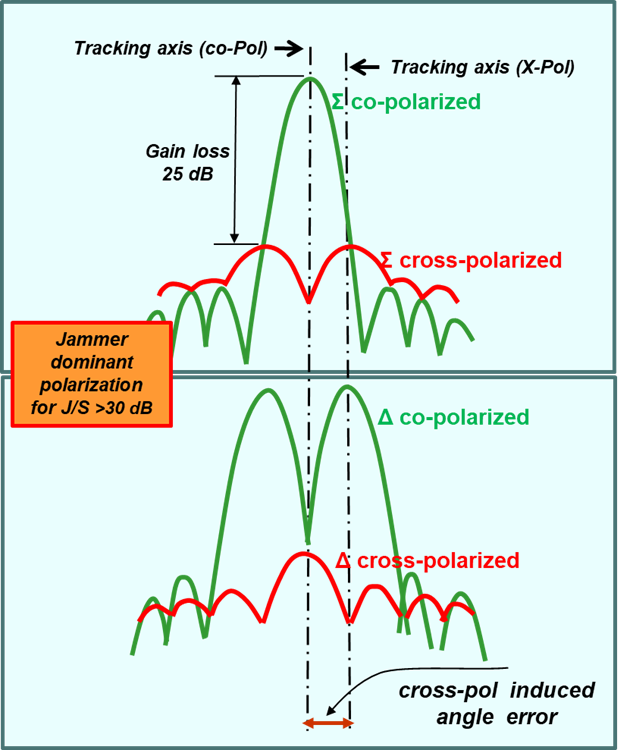
The cross- polarized jammer attempts to produce in the Δ channel a cross-polarized component that is large relative to the component with radar polarization, driving the error toward or beyond the peak of the Δ lobe at approximately half of the radar antenna beam-width.
Cross polarization exploits an intrinsic weakness of a mono-pulse antenna whose response to cross-polarized signals is significantly different from that of co-polarized signals as shown in the figure: the cross-polarized Σ beam shows a null in the direction of the bore-sight in addition to a structure of side lobes higher than the co-polarized beam.
On the contrary, the Δ cross-polarized beam has a maximum in the bore-sight direction.
If a cross-polarized jammer has enough radiated power (jammer-to- signal ratio of 30 dB) the received cross-polarized component is sufficiently stronger than the co-polarized skin echo.
Then the victim radar will be tempted to use the part of the cross-polarized pattern for the tracking and will move further away from the target (Figure 2).

Figure 2: Cross-Pol effect
In addition as the cross polarization pattern has relatively high side-lobes, disturbing energy could enter also from them and further disturb the tracking.
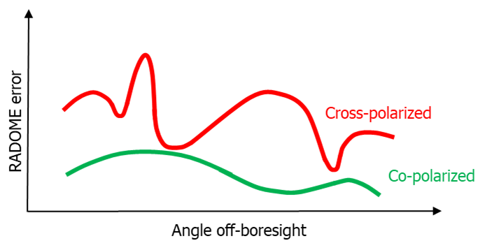
Further angular errors in the victim radar can be introduced by the aberrations of the Antenna Radome on cross-polarization waves (Figure 3).

Figure 3: Typical RADOME Error
There are generally two cross-polarization classes:
-
Non-adaptive, that do not have the ability to measure the polarization of the signal transmitted by the victim radar, therefore they need some a priori information or they try different polarizations in swept mode (Figure 4).

Figure 4: Typical Swept X-Pol sweep waveform
-
Adaptive, which use two cross-polarized receiving antennas to determine the polarization to be disturbed.
Cross-pol transmits noise-type signals or repeater type signals (coherent) and also repeater noise (noise modulation on a coherent seed, DRFM based).


