Wide Open Receiver in RESM
The Wide Open structure instantaneously covers the whole Radar RF spectrum (ΔF).
A Wide Open Receiver performs a detection on the entire operational RF Band before filtering; in this way it guarantees the possibility of revealing every pulse present (as long as it is in its “Dynamic range”, see Figure 3).
The most used Wide Open receiver was the crystal video receiver.
Its mathematical model is a quadratic detector that, having in input a sinusoidal signal, produces an output voltage proportional to the power.
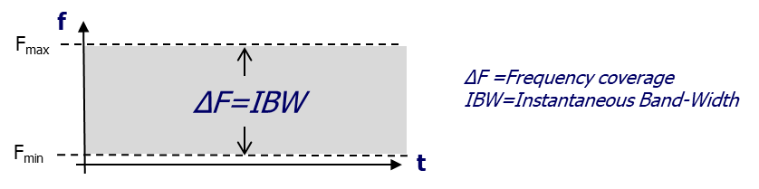
Figure 1: Frequency coverage of a Wide Band Receiver
In fact this corresponds to make the product of the signal by itself and then apply a low pass filter to the product.
Downstream of the Detection, a filtering (so-called “Video”) operates a “smoothing” of the detected signal to reduce its noise: the Video filtering band conditions the minimum detectable PW (Pulse Width).
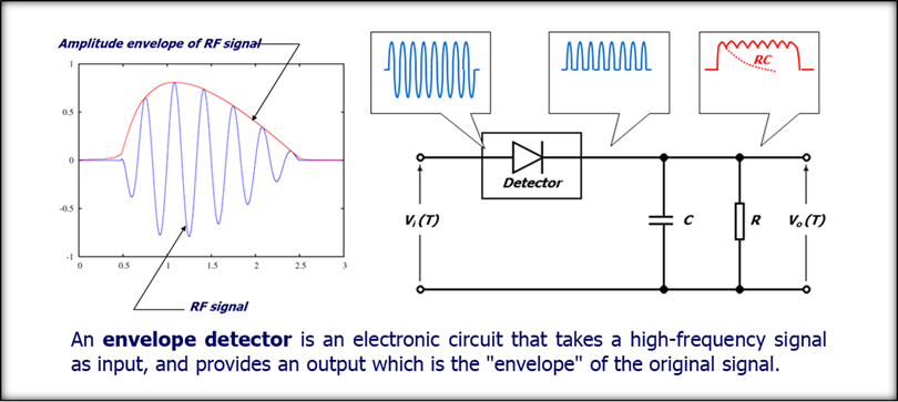
Figure 2: Amplitude based receiver: envelope detection
The video signal produced by the envelope detector loses any information relating to the RF carrier (frequency, phase, any modulations in the pulse) but contains information relating to the modulating signal (envelope) therefore it can only be used to extract the amplitude and, in case of pulsed signals, also the duration (Pulse Width, PW) and the Time of Arrival (TOA) of the signal.
The Detector is “intrinsically” non-linear, so in the case of multiple simultaneous signals it can create intermodulation that are in fact impossible to separate: the dynamics of a WO therefore always refers to the case of only 1 signal, while it is not considered in general the operation in the case of multiple signals.
- Detector Dynamic range:
Figure 3 gives the characteristic of a detector diode:- Below -50 dBm noise prevails and the device practically loses its detector characteristics.
- From -50 to about -20 dBm we are in the area where the quadratic law is valid.
The point where the real characteristic of the diode differs by 1dB from the ideal (straight line) is called 1dB compression point (P1dB) and represents the upper limit of the quadratic operation of the detector diode.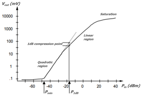
Figure 3: Detector characteristic
- From -20 to +20 dBm we are in the linear response zone of the device, in which the output voltage is proportional to the input voltage and therefore to the square root of the input power
The range of use of the detector as a power meter is the one in which the quadratic law is valid, therefore the typical dynamics of a detector is in the range of 30-35 dB and is intended for a single applied signal.
The Crystal Video receiver also allows the measurement of the Arrival Direction (DOA) thanks to a single Crystal video channel connected to a rotating antenna or to the parallelization of several channels connected to fixed antennas oriented in different directions to obtain a total coverage of 360 °.
In case of a rotating antenna the DOA is computed on the base of the trend of the amplitude over the time.
In case of multiple fixed antennas, techniques of amplitude or phase comparison can provide the DOA.
The crystal video naturally provides the amplitude, while another device is needed to obtain the phase comparison, similar to the frequency meter which uses interferometric techniques to evaluate the phase difference between two signals having the same carrier frequency.
The widespread use of non-linear devices in the following stages:
- the quadratic detector,
- the frequency meter,
- eventually the phase comparison,
makes the crystal video receiver able to operate on a single signal but not on co-pulses (overlapped signals over time).
The low sensitivity of the crystal video receiver, together with the proliferation of radar and communication signal, make this receiver suitable for short range application (like RWR).
On the other side the high POI and the simplicity of the receiver meet the requirement of the RWR systems and make this receiver useful for little platforms.
Frequency Measurement in the crystal video
In the most common cases, frequency information is required, therefore a frequency indicator, based on interferometric techniques, must be placed next to the crystal video.
The Instantaneous Frequency Meter (IFM) is a “phase detector” used properly to provide the accurate measurement of the frequency of oscillation of the incoming radio signal.
By processing the frequency values along the signal, it is possible to extract the value of the carrier, the phase of the signal and the internal modulation of phase or frequency.
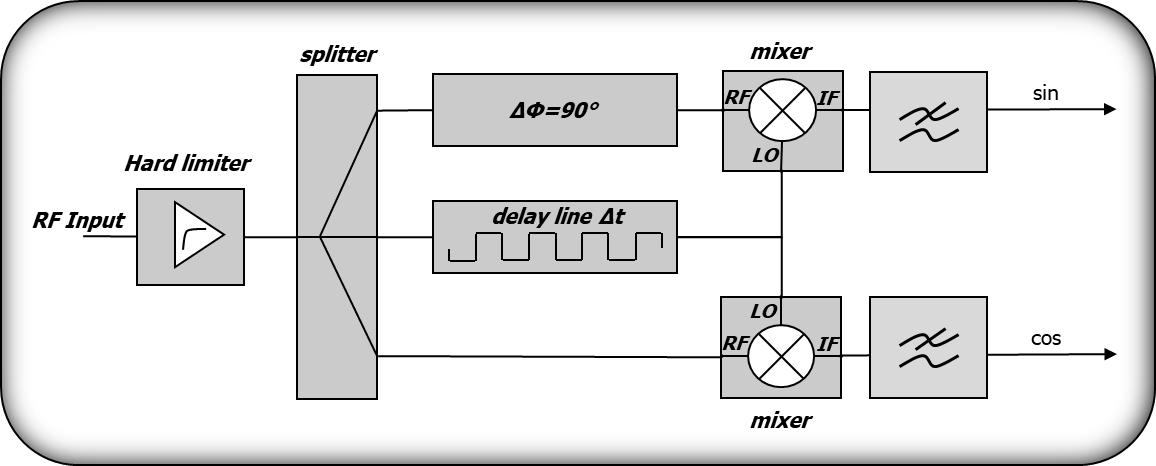
Figure 4: Basic block diagram of an IFM receiver
The main device in the interferometer is an IQ mixer, (i.e. a pair of mixers fed with the same signal, one of which is 90 ° out of phase to obtain the phase and quadrature components) followed by two low pass filters.
The second input signal of the mixers, the Local Oscillator (LO) input, is fed by the same signal delayed by a time Δt.
This device is capable of extracting the analog components of one signal with respect to the other, i.e. the two outputs provide the sine and cosine of the phase difference between the input signals.
This justifies the use of the interferometer as a phase comparator, in fact, because the second input signal is a copy of the first delayed by a time Δt, the difference in phase at the output is =2fΔt and is easy to extract the frequency as f=2Δt.
The components cos and sin can be transformed in the frequency or phase values by the mean of a sampling circuit that can output directly the phase or the frequency in digital format.
The input signal is hard-limited to ensure the IFM output to be independent from the signal amplitude.
Because the output phase value is subject to an ambiguity, multiple bases shall be used to resolve the ambiguity when the phase interval exceeds 2.
As shown in Figure 5, the EW analogue Wide Open RX is typically based on a single-channel IFM receiver with a multi – channel crystal video-envelope detector.
The upper chain is the IFM receiver that provides mainly the frequency estimation and, if required, the phase modulation.
The lower chain is the amplitude receiver whose aim is to estimate the amplitude, TOA, PW and the Direction of Arrival DOA.
The DOA estimation requires a number of antennas (at least 4 to cover 360°), each antenna requires a crystal video receiver as shown in the Figure 5.
The value of the DOA is carried out by comparing the amplitude seen by the antennas.
The last block, named PDM, is the PDM formatter that collects all the measures into the Pulse Descriptor Message.
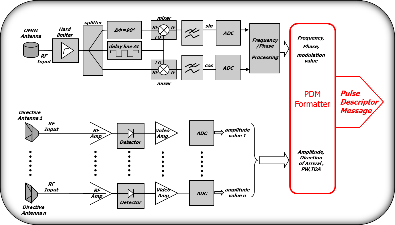
Figure 5: Typical Wide Open Receiver Architecture