Receiver Architecture in EW and ELINT
The architecture of the receiver is strictly dependent on the use of the passive sensors of which it is part; we can summarize three different applications that may require different receiver architectures:
• RWR (Radar Warning Receiver): monitors the frequency band (1-40GHz) typical of both radar-guided terminal threats (≃ 6-40GHz) and associated detection and designation sensors (≃ 1-8 GHz) in search of tracking radars aimed to the platform to be protected in order to produce an immediate alarm and activate possible countermeasures (Platform Self-Protection Suite, SPS)
• RESM (Radar Electronic Support Measures): expands (or integrates) the functionality of the RWR by searching in the typical frequency band 100MHz-40 GHz all the emissions of the search, designation and tracking sensors in order to produce a complete description of the situation (Electronic Order of Battle, EOB) by identifying and locating the operational sensors present in the scenario and activating the possible countermeasures
• ELINT (Electronic Intelligence): searches, analyses and records very accurately the parameters of radar emissions for intelligence purposes in the typical frequency band 100MHz-40GHz.
This data can be processed on-line or off-line to build a database of detailed information (characteristics of the radar waveforms) capable of being stored, in the form of an identification library, in the RWR / ESM sensors that will use them for recognition of enemy sensors.
Two types of analog receiver chains can be identified according to the relationship between their bandwidth (Instantaneous Bandwidth) and the total band to be received:
• Wide Band Receiver chain or Wide Open (WO) Receiver, which contains the main part of the Surveillance function and performs the Inter-pulse analysis.
The Wide band receiver chain covers instantaneously the whole radar RF spectrum (the instantaneous bandwidth is equal to the total bandwidth), so the Probability Of Intercept (POI) is almost equal to one.

Figure 1: Wide Band Receiver
It gives to the processor the necessary information for the execution of Radar Threats alert function: it must adopt some device or architectural artifice to protect it from very high Electromagnetic traffic.
• Narrow Band Receiver or Frequency Selective (FS) Receiver chain (usually called Super Heterodyne receiver, SH), which contains the hardware to perform the high precision measurement and the intra-pulse analysis (or MOP analysis), of detected emitters.
The super heterodyne instantaneously cover a limited portion of the spectrum and must be swept according to a given law (Receiver Search strategy RSS) in order to guarantee a full spectrum coverage (the instantaneous bandwidth is narrower than the total one); the RSS must be very “smart” in order not to decrease to much the Probability Of Intercept (POI).
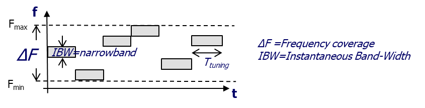
Figure 2: SH Receiver
align: leftCrossing the applications of passive sensors with the types of receiver chains, we can argue that a radar-warning receiver uses a WO receiver chain because POI is the most important performance for an alarm equipment.
An ELINT sensor can be based on a very selective receiver (FS) because the accuracy in the measurement of the parameters is the most important performance and the POI is not so important.
The RESM application is a bit more ambiguous because it requires almost the same POI and speed of reaction as the RWR and almost the same measurement accuracy as the ELINT.
The answer could be to have a mixed receiver composed both with the WO chain to get POI and speed of reaction and the SH chain to get very good measurement accuracy.
An alternative could be a channelized structure, where, by means of suitable contiguous filters, the total band is divided in many channels of the same narrow IBW as the SH receiver, each capable to measure signal parameters with high accuracy.
The parallelization of channels (each with almost 100% POI in its IBW) will give also almost 100% POI in the whole BW.
The drawback is that the channelized architecture is extremely expensive: this sensor in fact consists of n receiving channels placed in parallel, which should be multiplexed for the goniometric function on m antennas.
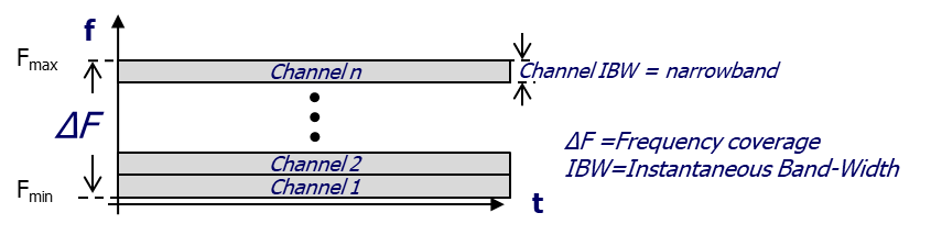
Figure 3: Channelized receiver
The use of current high-speed digital devices allows the creation of a broadband digital RF sensor.
It is known as Digital Receiver (DRX) that is a channelized RF sensor that uses digital techniques both in the discrimination (separation) of signals and in the measurement of the signal parameters.
Main devices used to make a DRX are:
• Analog to Digital Converter (ADC) with speeds and number of bits comparable to bandwidth and dynamic range requirements.
• Field Programmable Gate Array (FPGA) with the capacity and speed to support the required processing.
Numerical processing techniques allow:
• a simple implementation of the filter bank using solutions based on “Fast Fourier Transform” (FFT).
• the possibility of making accurate measurements by being able to operate on the numerical values of the Signal samples.
The bandwidth currently covered by a DRX allows it to be used as a SH receiver or as a single channel of a channelized receiver but since the performance trend of digital devices is constantly growing it is reasonable to expect its possible use as a complete channelized receiver in the near future.