Digital Receiver in RESM
A receiver for monitoring the electromagnetic spectrum has as its primary purpose the detection and characterization through measurements of the signals present in the electromagnetic spectrum.
Two types of receivers can be identified according to the relationship between their bandwidth (Instantaneous Bandwidth) and the total band to be received: Wide Open Receiver and Narrow Band Tuneable receiver.
Wide Open receivers have advantages in terms of Probability of Intercept (POI) while the tuneable ones have higher sensitivity due to the narrower instantaneous band.
In addition, tuneable receivers can protect themselves from jamming noise by shifting in frequency.
The transition from analog receivers to digital receivers has been gradual with the increase of sampling rates with respect to signal bandwidth: initially only the video signal was digitized, then also the IF signal and finally the RF signal.
The video digitization, even if cannot be strictly considered part of digital receiver family, is the oldest type of digitization in an EW receiver.
There are numerous variants of this which, however, can be traced back to the two described below.
In the Wide Open version, the RF signal is passed through a non-linear device (called detector) that extracts the video signal, i.e. the RF envelope (Figure 1).
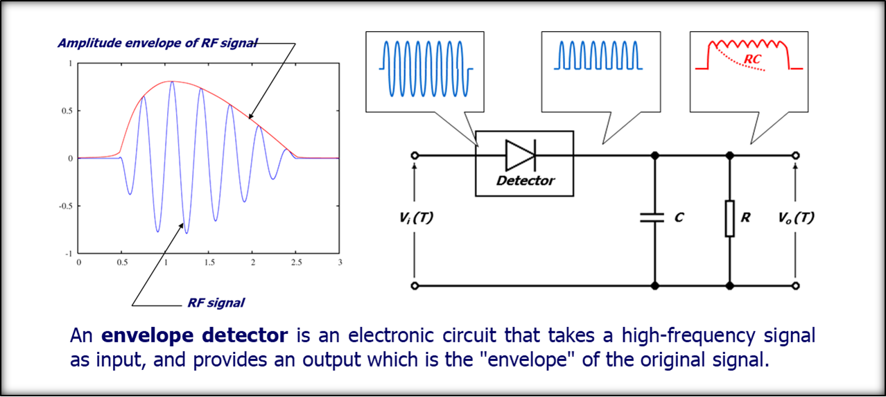
Figure 1: Amplitude based receiver: envelope detector
The video is sampled and the measurements of amplitude, time of arrival and duration are made on it.
The measurement of the signal carrier frequency cannot be extracted from the envelope and a specific device must be used that provides the frequency in digital format by using interferometric techniques.
In the tuneable version, the RF is converted into an IF frequency, whose bandwidth is equal to the instantaneous band.
The IF signal is treated as in the previous case, i.e. the envelope is extracted and digitized to perform the measurements and the frequency measurement is obtained with interferometric techniques.
The advantage and defect of this receiver is the envelope detection: in fact it guarantees a large bandwidth but, being non-linear, it prevents detecting contemporary signals because the stronger signal prevails, hiding the others.
This is particularly annoying when a strong CW signal blinds the receiver or forces sensitivity to deteriorate.
Some techniques of Sub-CW visibility can be implemented but only in the presence of pure CW (not ICW) and in any case, they do not guarantee to go below 15-20 dB compared to CW.
The ability to sample the signal, in the years 2000s, at frequencies of the order of GHz has allowed to sample the IF signal.
In this way, a generation of tuneable digital receivers with instantaneous bands of 500 MHz was born.
The architecture of these receivers arises from the need to operate in high dense traffic conditions (i.e. often with overlapping pulses) and is based on a digital filter bank (Figure 2).
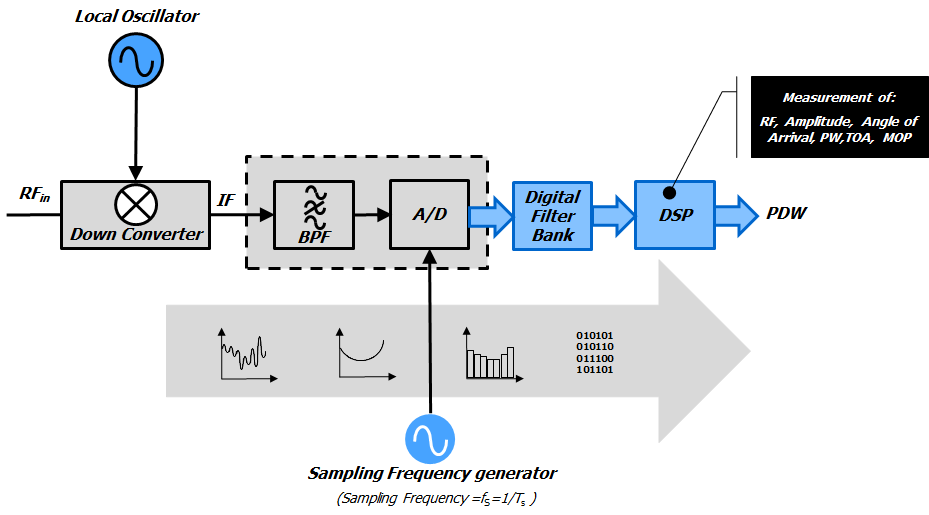
Figure 2: DRX functional scheme
Immediately downstream of the sampling there is a bank of filters, that use FFT (Fast Fourier Transform) algorithms, which divide the instantaneous IF bandwidth into bins.
The width of these bins must be chosen carefully taking into account the sensitivity, the minimum duration of the signal and the frequency resolution to be obtained.
The filter bank is followed by a detector bank that extracts the signals.
The parameter measures that characterize the pulse are extracted from the DFT (Digital Fourier Transform) samples in the bins in which the signals are present.
To obtain the measurement of the direction of arrival that is a differential measurement, EW systems need, whatever the Direction Finding (DF) used, two or more of these receivers synchronized with each other.
The evolution of this type of receiver is linked to the increase of the sampling rate and the processing capabilities, which allows enlarging the instantaneous band.
From an algorithmic point of view, smart detection algorithms are used to increase the instantaneous dynamics.
Today digital receiver performance is conditioned by the performance of the ADC (analog-to-digital converter), which guarantees a sampling frequency in the order of 6.5 GHz with a resolution of 12 bits typical.
If on one hand the architecture described for a digital receiver satisfies the needs of tuneable receivers, on the other hand, solutions are sought for Wide Open receivers: the obtainable band with an ADC of the aforementioned type provides an instantaneous band of 2 – 2.5 GHz by taking into account the transition zones of the anti-aliasing filters.
In order to cover bands of 10 – 20 GHz, as required by WO receivers, it is necessary to find other solutions that allow in any case detecting and measuring contemporary signals separately.
The attempt to extend the sampling frequency in order to guarantee instantaneous bands of the required type does not seem to be feasible today because the current sampling systems have already by themselves (i.e. without the processing system) dissipated power and dimensions incompatible with the installation requirements
A solution that is currently accredited is to move towards subsampling techniques which consist in using receivers that operate in aliasing conditions.
For the type of signals we are considering, i.e. narrow band signals which are spread over a very large frequency range, the aliasing appears as an ambiguity of the carrier frequency as seen downstream of the sampling (apparent frequency).
This frequency ambiguity is resolved by using multiple sampling systems in parallel which, after channelling, feed an ambiguity resolution algorithm.
Techniques of this type, already tested in the past for frequency measurement, as the mono-bit receiver, can be used with current sampling systems to obtain receivers having the bandwidth compatible with Wide Open receivers but capable of distinguishing contemporary signals.
The sensitivity of these receivers is lower than that of tuneable receivers due to the aliasing phenomenon that causes the noise spectrum to fold into the sampling band.
The solution just described requires to extend the analog bandwidth of the sampling systems beyond what is currently available since it is required to directly sample the RF signal.
The solution is to precede the ADC by an S&H (Sample and Hold) having the required analog bandwidth so that the assembly of the two components behaves as a single ADC with extended performance.
The possibility of having analogue bands compatible with radiofrequency suggests a further step in the digitization of tuneable receivers: the step consists in directly sampling the RF signal.
By doing so, tuneable receivers and WO receivers are obtained starting from the same sampling system and are distinguished only by their behaviour with respect to aliasing.
As to date, a sampling system capable of operating on RF without aliasing would be not convenient; we can hypothesize two alternative ways of operating:
- Folded receiver: it uses at the same time multiple sampling frequencies and algorithms of resolution of ambiguity.
- Direct sampling tuneable receiver: it is based on an “extended” sampling theorem, in accordance to which there is no ambiguity if a signal remains in a band between integer multiples of fc/2.
The first of the above two receivers represents the alternative to the WO receivers, while the second one represents the alternative to tuneable receivers.
The following Figure 3 shows a single channel of a tuneable or folded digital receiver.
The down conversion is no longer present because the pair Sample & Hold plus A/D can operate at the higher RF frequencies. The band pass filter (BPF) selects the tuning band of the tuneable receiver or the operating band of a folded receiver.
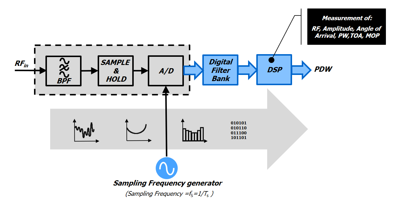
Figure 3: Direct sampling DRX
With regard to the RF section of these receivers, the following should be noted:
- Envelope detectors are not any more used and this guarantees both the linearity of the receivers as well as the ability to separate simultaneous signals.
- The unnecessary frequency conversion of the direct sampling has been removed.