Radar Warning System
The RWR is the simplest and lightest ES warning sensor and as such is installed on board of all the military platforms. It usually consists of four Receiving (Rx) Antennas displaced at 90° from each other to provide the Direction Finding (DF) function and a Receiver/Processor Unit (RPU) that provides threat warning detection, bearing and proximity data to the platform crew monitor.
The RWR is used for identifying, avoiding, evading or engaging threats [1].
The typical RWR system (Fig. 1) consists of multiple wideband antennas (Direction Finding (DF) and an Omni –directional antenna (most times synthetically provided from the DF ones)) placed around the defended platform, a Frequency Receiver, an Emitter Library and a Display.
The receiver is normally a SuperHet one with a suitable scanning strategy and periodically scans a limited bandwidth (currently up to 2 GHz) across the total frequency band (usually 0.5 to 18 and 30 to 40 GHz) to determine the parameters of the received signals, such as frequency bandwidth, signal shape, direction of arrival, pulse duration and repetition frequency, etc.
By using these measurements, the mixture of incoming signals are first de-interleaved to sort out the various emitters present in the environment.
These data are then compared with the Emitter Library contents to determine the threat dangerousness and priority and displayed on the platform visual display/on board processor.
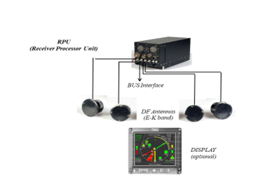
Figure 1: Possible RWR configuration
The airborne RWR usually has a visual display somewhere prominent in the cockpit (in some modern aircraft, in multiple locations in the cockpit) and also generates audible tones which feed into the pilot’s (and perhaps RIO/co-pilot/GIB‘s in a multi-seat aircraft) headset.
The visual display often takes the form of a circle (Polar representation), with symbols displaying the detected radars according to their direction relative to the current aircraft heading (i.e. a radar straight ahead displayed at the top of the circle, directly behind at the bottom, etc.).
The distance from the center of the circle, depending on the type of unit, can represent:
- the estimated distance from the generating radar, or
- the dangerousness of threats to the aircraft, with tracking radars (more immediately dangerous) placed far from the center than search radars (less immediately dangerous).
The symbol itself is related to the type of radar or the type of vehicle that carries it, often with a distinction made between ground-based radars and airborne radars.