Digital Radio Frequency Memory DRFM for ECM applications
Since modern radars exploit coherent processing, modern ECM must equally exploit coherent techniques.
The key element to implement coherent ECM techniques is the Digital Radio Frequency Memory (DRFM).
The DRFM is the core of a super-heterodyne selective receiver that is the basic response channel architecture in any jammer system where a narrow band of signal has to be handled at time for jamming purposes.
A DRFM is designed to digitize an incoming RF input signal at a frequency and bandwidth necessary to adequately represent the signal, and then reconstruct that RF signal when required.
In addition to this, the use of digital techniques offers other opportunities that improve the performance of RF memories and countermeasures in general.

Figure 1: DRFM principle of operation
Among the main ones we remember:
-
The transformation of the signal into digital form, necessary to use the RAM, makes it possible to use digital processing techniques in order to increase the quality of the transmitted signal and with it the amount of jamming energy captured by the victim radar.
-
The modulation of the signal was implemented with digital techniques, enriching the repertoire of modulation techniques and increasing its accuracy, all this to generate signals similar to those reflected by the targets.
-
The signal stored digitally lent itself to being saved on mass memory in order to perform off-line processing for electronic intelligence applications
-
The digital management of the DRFM + modulators assembly made it possible to improve multi-threat performance by being able to alternate reception and transmission phases to and from different radars and allowing the DRFM to generate a large number of false targets even when engaged against multiple radars.
The improvement due to the use of digital techniques is still ongoing since both the processing algorithms and the HW devices are constantly evolving, the goal is to improve the spectral purity of the DRFM, implement new ECM techniques and reproduce increasingly realistic signals.
The spectral purity of the reproduced signal is essential because it brings the following advantages:
-
Reduction of the “signature” of the DRFM, i.e. elimination of the spurious spectral components that make the transmitted signal distinguishable from that of a real target.
-
Optimization of the power “seen” inside the radar by eliminating unwanted spectral components that subtract power from the signal transmitted by the ECM system but which the radar eliminates with its processing.
The most significant aspect of DRFM is that, as a digital “duplicate” of the received signal, it is consistent with the source of the received signal.
Moreover, it can act as a waveform synthesizer (non-coherent replicas).
A DRFM is capable of implementing coherent techniques (coherent replicas of the received signals) and is provided with complex programming capabilities (Technique Generator DSP based) that allows multiple false echoes with complex apparent kinematic laws and waveform synthesis.
A coherent replica consists in using the same signal received from the threat radar as the seed of the jamming signal, in this way the jamming signal will be not distinguishable from the true echo and will be processed with the same processing gain (increasing the J/S ratio).
Coherent replicas are used in deception techniques to change the range by transmitting pulses with changed delay with respect to the true echo (Range Gate Pull Off/Pull In) or the speed by transmitting signals with changed Doppler shift with respect to the true echo (Velocity Gate Pull Off/Pull In).
The signal stored in the DRFM can be used also as the seed of a noise modulation, in this way Spot Noise is adapted to radar instantaneous frequency bandwidth or to Doppler bandwidth (coherent Spot noise).
The intent of this technique is to reduce the victim radar’s ability to measure and track the target’s Doppler by producing a noise Doppler band centred on the target’s real Doppler (e.g. to mask semi-active seeker speed gate).
The use of the received and stored signal as RF carrier (to produce coherent noise) instead of the use of locally synthesized RF carrier (non-coherent noise) will increase the Jamming Noise performance, giving a much better matching with the radar BW (this is crucial in case of coherent radars).
Jamming Noise performance can be defined in terms of global S/N reduction when jamming is added to noise (signal to noise plus jamming ratio).
It depends upon the matching between the jamming signal and the true echo (how much of the jamming signal is able to enter the radar matched BW without being attenuated by the radar processing gain?) and how much the noise characteristics can be assumed similar to thermal (Gaussian) noise.
A Noise Quality Index (NQI) can be defined, which depends by the closeness of the jamming noise to Gaussian characteristics and by the ratio between the jamming BW and the radar matched BW (a good noise quality is obtained with a minimum jamming BW to Radar BW ratio of a factor 3).
Continuous Noise generation in repeater mode requires periodical look-through or alternate RX-TX operation to tune jamming carrier to threat RF, to receive, to store and to process it before transmission (coherent jamming).
As said before to make coherent jamming the incoming signal must be received.
If the pulse characteristics do not change with time we can use a pulse received in the past to produce the present coherent replica.
Instead, if the pulse characteristics change, we are obliged to receive all pulses, but if the Jammer acquires the whole pulse, transmission is blocked during the acquisition phase and it is impossible to generate False Targets closer than PW.
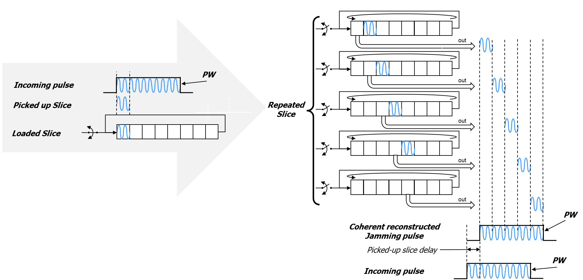
Figure 2: DRFM functional mode: Slice Repeater
A way to overcome the problem is the Slice repeater (Figure 2).
Slice repeater is a coherent DRFM functional mode capable to reconstructing a coherent jamming replica using only a little part (slice) of the incoming signal (Figure 3).
This will allow receiving only for a while and transmitting before the end of the incoming pulse: the alternation between RX and TX operation is made inside the pulse only once.
This technique allows coherent acquisition and replaying operation producing replicas with fast Phase and frequency coherency in order to ensure an enough good correlation (matched filtering) in radar receiver.
The timing illustrated in Figure 3 is theoretical because does not take into account the process latency and the delay due to the HW electrical path.
The challenge will be to reduce these parameters as much as possible together with obtaining the best phase coherency in the re-stitching of the various signal slices.
Of course, intra-pulse modulation presence puts constraints and limitations.
If only a fraction of the pulse is acquired, a degradation occurs, because jamming pulse is not compressed in the proper way.

Figure 3: Slice repeater operation