Passive Direction Finding [DF] Techniques – General
![2154Passive Direction Finding [DF] Techniques – General](https://www.emsopedia.org/wp-content/uploads/2021/03/iStock-1187184065.jpg)
The purpose of radio-goniometers is to find out the Direction Of Arrival [DOA] of an incoming RF emission.
The measurement of the angle1 is an indirect one:
the radio-goniometer provides its estimate by inferring an electrical parameter of the emitter.
Emitter parameters that are used by EW Systems for Direction Finding (DF) purpose are:
-
Amplitude (Figure 1)
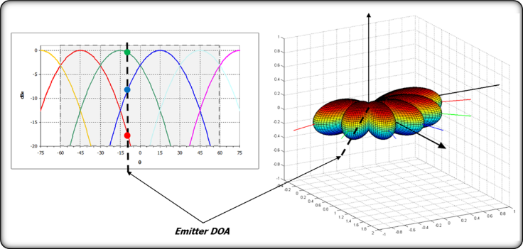
Figure 1: Amplitude DF Technique
-
Phase (Figure 2)
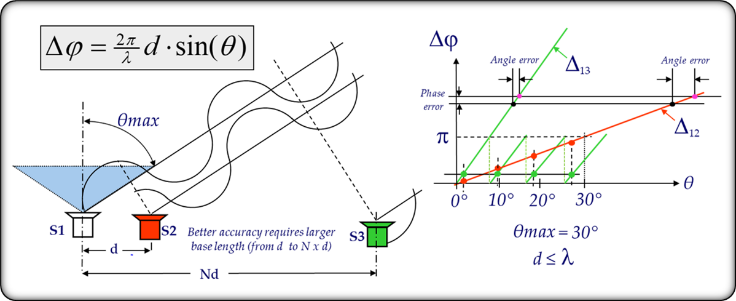
Figure 2: Phase DF Technique
-
Time Of Arrival [TOA] (Figure 3)
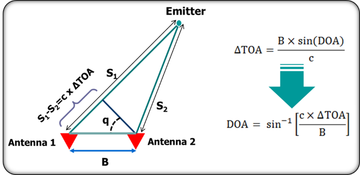
Figure 3: TOA DF Technique
Hence, we can classify DOA measurement techniques according to the parameter used to make angle measurement.
Dedicated entries, will present each specific technique; mainly some emphasis shall be put on following aspects:
-
Signal Parameter
-
-
The Signal Parameter chosen could impose strong constraints on the kind of Receiver [Rx] to be used in the so called “DF Channels”2;
-
-
-
-
As an example, the Amplitude can be measured using a simple Crystal Video Rx whereas the Phase needs an Interferometer or (as usual in modern EW Systems) a Super-Het Rx.
-
-
-
Requirements/Issues on the EW System.
-
-
Each technique usually imposes, according also to the needed performance, the following constrains on the hosting EW system
-
-
-
-
Number of Antennas:
-
-
-
-
-
-
As we will see in dedicated entries, the number of Antennas is relevant to both the spatial coverage and the DF accuracy.
-
-
-
-
-
-
Number of DF Channels:
-
-
-
-
-
-
From a conceptual point of view, each Antenna should be connected to a receiving channel but, in order to reduce complexity/cost of the whole EW system, the actual number of DF channels can be less than the number of antennas.
N Antennas can be routed to M DF Channels through a Beam Forming Network [BFN], e.g. a proper combination of the Antennas, or through switching, e.g. by connecting the same channel to different Antennas in time-division.
-
-
-
-
-
-
Calibration:
-
-
-
-
-
-
The DF Function is based on the measurement of the same signal “seen” by different Antennas (mono-pulse measurement).
In order to do that the EW System should be able to perform a theoretically exact differential measurement; obviously, this is not possible because, in order to make a differential measurement, we should need identical DF channels.
One of the challenges in the design of practical DF systems is the calibration needed to make as equal as possible DF Channels.
In some cases, Calibration is carried out by means a proper manufacture and/or with the aid of calibration tables recorded in factory and loaded on the EW System.
Sometimes the Calibration is instead so demanding that the EW System incorporates a sub-system dedicated to perform an “on line” calibration in order to eliminate any possible differentiation among the channels (different H/W aging, different temperature, different vibration level, etc.).
-
-
-
-
-
-
Synchronisation:
-
-
-
-
-
-
The synchronisation topic is conceptually similar to that one of calibration, but when the latter is referred typically to the analogue part of the Rx the former is focused on the matter of synchronising the digital part, (Analog-to-Digital converters, processing engines, etc.).
-
-
-
-
-
-
Kind of DF Channels:
-
-
-
-
-
-
As above mentioned in some cases the type of Rx channel can be constrained by the Signal Parameter but this choice depends also upon by other factors some related to the DF Technique itself (accuracy, number of channels, Calibration/Synchronisation performances, etc.) others related to different performance of the EW System (Sensitivity, ability to operate in dense environments, etc.)
-
-
-
-
Typical DF performances
-
-
The different kind of EW system can have different requirements in term of DOA estimation performance according to:
-
-
-
-
Their nature (e.g.: RWR, ESM, ELINT, etc.)
-
Specific Customer Requirements
-
-
-
-
According to the desired DF performance a specific Technique can be adopted during the design of the EW Systems
-
Each DF Technique allows the reaching of a range of performances which must be known in order to let EW engineers able to make the correct trade-offs in the design phase
-
-
“Pro/Cons”
-
-
Each DF Technique does have its own pro and cons: trade-offs have to be always done but we have to do this not looking only at the DF Technique itself but also taking into account several aspects.
-
-
“Impact on Platform”
-
-
EW Systems can be installed in ground, sea or air platforms.
-
The DF Technique, as previously mentioned, is strongly related to the so called “Antenna Farm” (e.g. the whole set of Antennas belonging to an EW System): since different DF Technique could lead to different impact on the hosting platform, the ability to be installed onto a given platform (in particular for naval and airborne cases) can become a crucial issue.
-
1 Even if the DOA should be represented by two angles (Azimuth/Elevation or θ/φ) in most of cases radio-goniometers, provide only the Azimuth.
2 With the term DF Channel is meant the receiving channel used to provide the measurement of the signal Parameter used to estimate the DOA.
![Passive Direction Finding [DF] Techniques – Phase Comparison](https://www.emsopedia.org/wp-content/uploads/2021/04/iStock-545810334.jpg "Passive Direction Finding [DF] Techniques – Phase Comparison")

")