Electronic Protection (EP)
Electronic Protection techniques are often employed in radars against RECM and in radio networks against CECM.
EP in Radar field
There are two broad classes of EP techniques:
• Electronic techniques
• Operational doctrines.
Surveillance and tracking radars are equipped with a suitable blending of EP techniques.
A large number of EP techniques have been known and quoted in the literature since 70’s and the number is continuously increasing with the progress of radar design.
In the radar field, the benefits of using EP techniques may be summarized as:
• Prevention of radar saturation.
• Enhancement of signal-to-noise or signal-to-jamming ratio.
• Discrimination of directional interference.
• Rejection of false targets.
• Maintenance of target tracks.
• Counteraction of ESM, and radar system survivability.
Specific electronic techniques take place in the main radar subsystems, namely antennas, transmitters, receivers and signal processors.
- EP techniques in Radar Antennas
- In the radar antenna, ultralow side lobes, side lobe blank (SLB), and coherent side lobe cancellers (CSLC) are the main line of defence to restrict the radar jamming to the antenna main lobe.
- Side Lobe Blanking:
The purpose of a SLB system is to prevent the detection of strong targets and interference pulses entering the radar receiver via the antenna side lobes.
A method of achieving this is to employ an auxiliary antenna coupled to a parallel receiving channel so that two signals are available for comparison (Figure 1).
By suitable choice of the antenna gains, it is possible to distinguish signals entering the side lobes from those entering the main beam, and the former can be suppressed (Figure 2).
- Side Lobe Blanking:
-
-
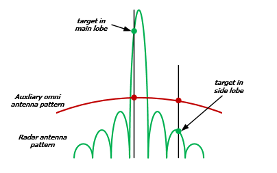
Figure 2: SLB principle of operation
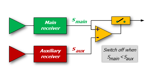
Figure 1: Example of SLB receiver
-
-
-
-
- Side Lobe Canceller:
The objective of the sidelobe canceller is to suppress high duty cycle and noiselike interferences (e.g. from SOJ) received through the side lobes of the radar.
This is accomplished by equipping the radar with an array of auxiliary antennas used to adaptively estimate the direction of arrival and the power of the jammer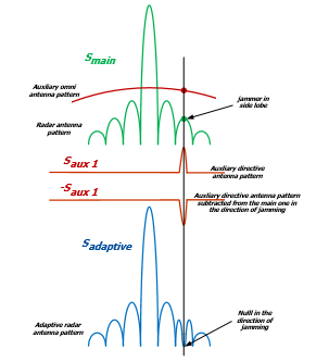
Figure 4: SLC principle of operation
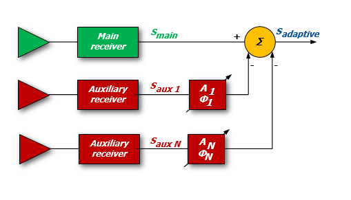
Figure 3: Example of SLC receiver[/captio
- Side Lobe Canceller:
-
-
-
- Frequency agility strongly reduces Noise Jamming Effectiveness because the jamming power has to be spread in a very large bandwidth.
- EP Techniques in Radar Receivers
EP in the radar receiver is aimed at preventing receiver overload that would suppress target signals.
This form of EP generally involves some form of receiver nonlinear operation or AGC/STC control.
Logarithmic receivers, Dicke Fix receivers, or Guard-band receivers are example of this type of EP.- Dicke Fix is an ECCM technique used to counter high rates of swept frequency CW, swept spot noise jammers and other related swept ECM techniques.
Also known as Lamb suppressor or Amplitude frequency selection, it uses wide band IF amplifier and a limiter ahead of the normal IF amplifier of a radar receiver, so that the recovery time from the effects of a swept jammer can be rapid.
The wideband amplifier seeks to ensure that no jamming pulse widening or stretching takes place and the jamming effect is limited only to the amplitude and not to the width of the jammer signal.
Dicke Fix is also used as a CFAR technique.
- Dicke Fix is an ECCM technique used to counter high rates of swept frequency CW, swept spot noise jammers and other related swept ECM techniques.
- EP Techniques in Radar Signal processing
- Pulse compression generally provides a processing gain over noise jamming equal to the pulse compression ratio τ B (τ is the radar pulse-width and B is the transmitted bandwidth).
- Low probability of intercept (LPI) waveform design attempts to prevent the jammer from intercepting the radar signal, which in turn inhibits the EA jammer from initiating a jamming response.
- Anti-Gate-Stealing:Deception techniques against tracking radar are initially directed toward capturing the range and the speed (if appropriate) gates of the tracking radar (Range Gate Pull-Off, RGPO and Velocity Gate Pull-Off, VGPO).
During this process, the radar loses range and velocity information but still tracks the target in angle.
After the capture of the range (and/or speed) gate, the jammer applies angle deception to cause the tracking radar to break lock.
Range tracking is carried out in pulsed radar by direct matching of a range gate position to the delayed echo pulse.
An Automatic Gain Control keeps the received signals at the foreseen level for tracking loops stability, sampling the signal at the centre of range gate.
The usual technique is the split-gate range tracker, which is a form of range tracker using a pair of time gates called an early gate and a late gate, contiguous or partly overlapping in time.
When tracking is established, the pair of gates straddles the received pulse that is under track.
The position of the pair of gates then gives a measure of the time of arrival of the pulse; that is, the range of the target from which the echo is received.
This process is vulnerable to jamming that is capable to enter in the gate and to move it (Figure 6). -
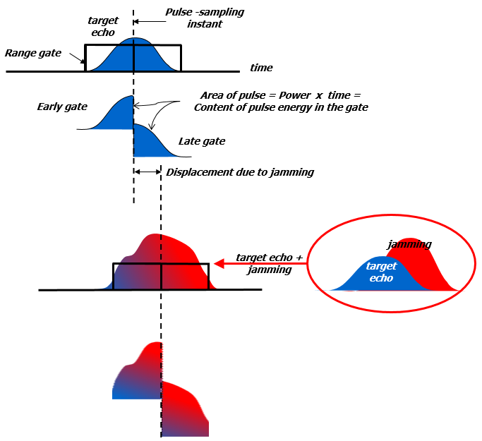
Figure 6: Effect of Jamming in a centroid gate
-
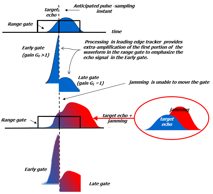
Figure 7: Effect of Jamming in a leading Edge gate
The first EP defence against this type of jamming is to prevent the tracking radar’s gate from being captured.
The alternative technique is the Leading Edge Tracking (LET).
LET is an ECCM technique for use on a pulse range-tracking radar that obtains range track on a target return by detecting and tracking only its leading edge by means of using a different gain of processing in the two portions of the range gate (early gate is weighted much more than late one).
This technique is employed to exploit the unavoidable delay associated with repeater jammers (Figure 7).
Best time discrimination must be traded with worse noise susceptibility (a smaller part of the echo signal is used causing a worsening of the Signal-to-Noise ratio).
EP in Radio Communications field
Electronic Protection in radio communications is also known as Transmission Security (TRANSEC) that aims to perform a sort of ECCM, limiting the effects over the radio receivers of both intentional and not-intentional radio interferences.
For the radio communication, the Electronic Protection is a matter of the defence from any sort of threat coming from RF emissions.
In a general view, through a RF emission aiming to affect some radio devices or part of networks, the threat can target different parts of the overall information flow.
In fact, via RF signals, an attacker may target the transmission quality in order to impair the receiving capability of the targeted radio devices but with the same RF signal, a Cyber Attack may be started, aiming either to take the control of the network or to trigger a “0-Day” cyber-attack. While a cyber-attack addresses data and process impairment due to threats input via both wired and wireless media, it does not refer the threats exploiting their effect against the link/network physical propagation capability, being it wired or wireless based.
Here, just the physical aspect of the RF transmission is at the stake, and then TRANSEC is the subject of this section.
As the radio interferences aim to impair the radio receivers featuring radio links, these devices limit the negative effect by spreading the link signal energy through a wide range of frequencies.
This energy distribution, pseudo-casually performed, constrains the ECM to generate quite high power level jamming signals in order to input into the target receiver enough J/S values at the possible channels distributed over the frequency range.
Then the EP relies its effectiveness on the energy spectrum inefficiency in which the ECM is constrained. This ECCM capability may be performed by adopting one or both the following techniques:
- Spread Spectrum;
- Frequency Hopping.
Spread Spectrum, generally known as Direct-sequence spread spectrum (DSSS), is a modulation technique that makes the transmitted signal quite wider in bandwidth than the information bandwidth.
The modulation is performed digitally by acting over the message bits that are modulated by a pseudorandom bit sequence known as a spreading sequence.
Each spreading-sequence bit, which is known as a chip, has a much shorter duration (larger bandwidth) than the original message bits (Figure 8).
The modulation of the message bits scrambles and spreads the data over a higher data-rate s equence, thereby distributing the information in a bandwidth size nearly identical to that of the spreading sequence (Figure 9).
The smaller the chip duration the larger the bandwidth of the resulting DSSS signal providing better resistance against interference.
Each receiver featuring the EP technique is able to de-spread the signal energy by removing the direct-sequence modulation and then recovering the information.
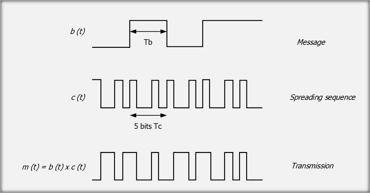
Figure 8: message modulation
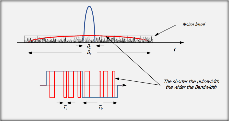
Figure 9: energy spread over a wide spectrum
The efficiency of any unintentional or intentional interference will be highly reduced, as the J/S will drop due to the jammer spectrum inefficiency and to the high correlation gain performed by the de-spread of the pseudorandom sequence (Figure 10).
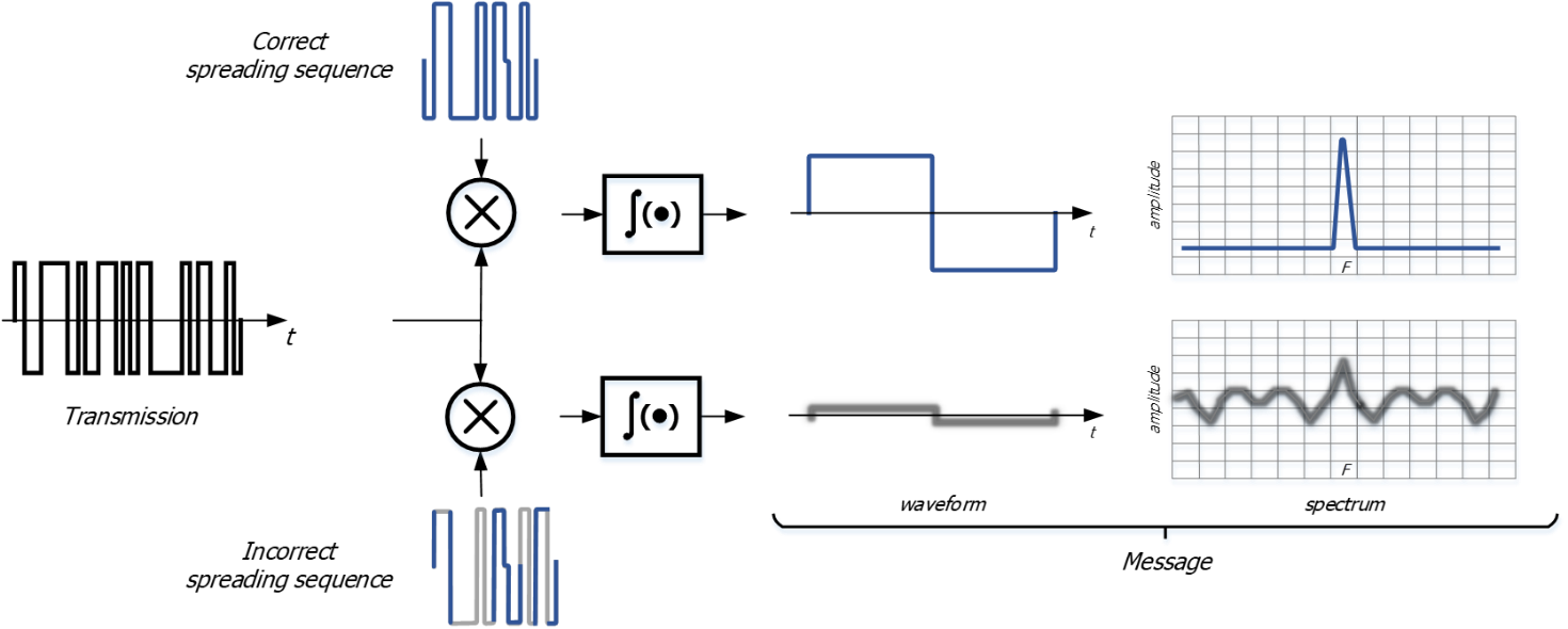
Figure 10: De-Spreading autocorrelation function
Frequency Hopping (FH) generates a modulated carrier changing its centre frequency according to a pseudo-random positions set, or hop set.
Each centre frequency is kept along a period T including the on time for the RF emission and the off time for the next frequency setting.
The shorter the period T (the higher the Frequency hopping rate) the shorter will be the time available to the ECM to affect the TRANSEC based link over the tuned frequency.
The period T is called “Dwell-Period” as this time includes both the “on” and “off” time.
During each Dwell-Period.
During each dwell, the transmitter will transmit the RF modulated carrier for a nominal dwell time, or on time.
Preceding each dwell time there is a nominal off time allowing for either switching or setting of frequency-sensitive components (e.g. synthesizer tuning).
The frequency hopping rate, or FH [hop/s], states the performance of the TRANSEC waveform where higher hopping rate make quite difficult for the jammers to generate ECM signals with enough J/S, timely and frequency tuned, over the instantaneous hop.
FH is adopted generally over digital modulated signals, where Fast FH (FFH) may be at hop rate so high to transmit just some user bits during a single dwell time.
In the military application, the TRANSEC technique is widely adopted, mainly for sensitive missions, over a wide frequency range, from HF and VHF up to upper values of UHF (some GHz).
The hopping rate ranges in value from some hop/s to some tens of thousands hop/s.
Generally, the RF transmitted signal adopts the same modulation and data rate in each dwell, thus generating the same bandwidth around the changing carrier position.
Each FH system is designed to tolerate a maximum timing uncertainty between transmitter and receivers, and all users’ terminals must remain within this tolerance for the duration of the mission.
Figure 11 depicts the timing management and shows the synchronization between the Data Management and the tuning according to the dwell period features, keeping each participating terminal synchronized with each other in the network.
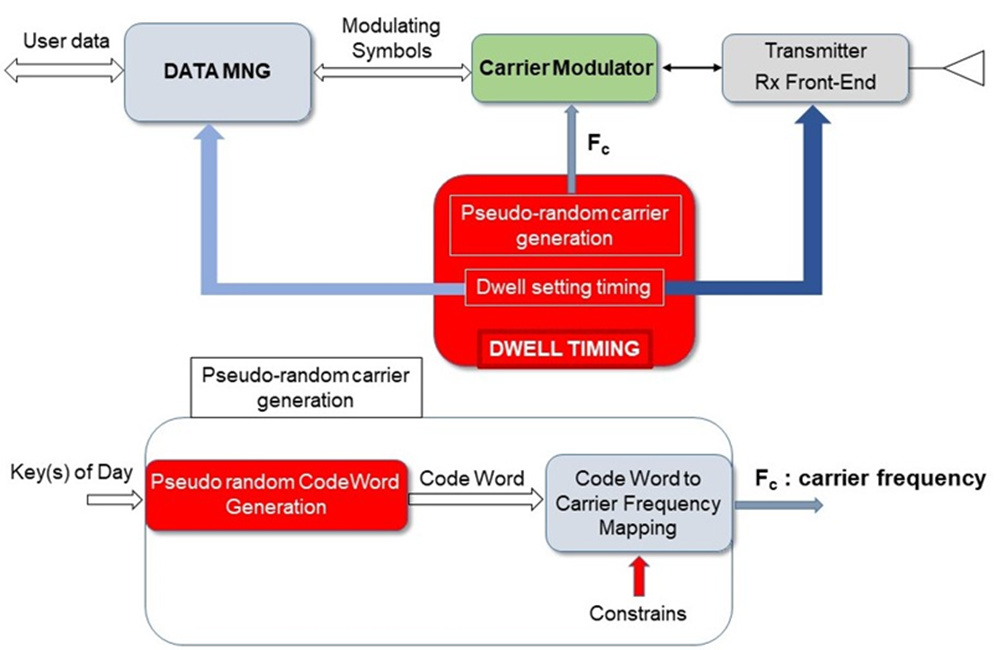
Figure 11: Dwell Timing and Frequency carriers management
Each radio terminal participating to the FH network adopts the same hopping sequence locally generated by a common algorithm operated in turn by using some common keys (Figure 11).
Uncooperative terminals will find quite random and unpredictable frequency carrier’s positions, and then the algorithm and the keys adopted provide the users with an effective protection against the jammers.
The keys setting the pseudo random code-words generator are generated daily according to the specific day and time of the mission.
Each generated code word is associated with a specific carrier frequency and adopts a mapping that is imposed by certain system constraints also related to the network users and their usage requirements.
Relying on a common timing, the network participating terminals synchronously tune their own carrier over the same frequency position, where this value is one of the tuned frequencies included in a common hop set (Figure 12).
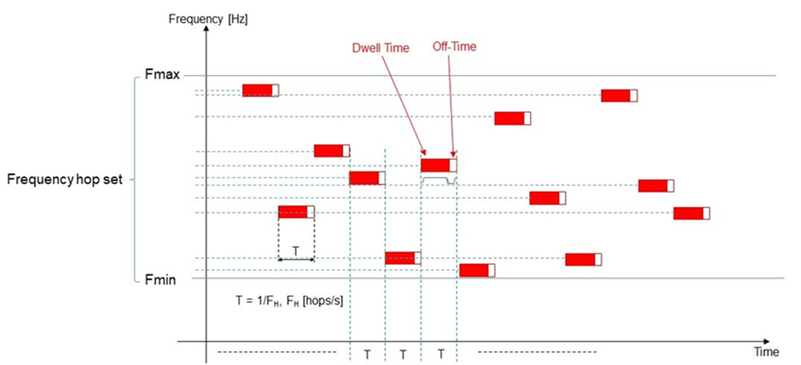
Figure 12: Frequency Carriers sequence